555 Timer Schematic - 555 Timer Monostable Circuit Diagram : The 555 is also very versatile, and can be used.. The block diagram of a 555 timer is shown in the above figure. Each mode of operation indicates a circuit diagram and its output. 555 datasheet 555 duty cycle 555 metronome 555 reset function 555 time delay relay inverted 555 timer pulse generator. As discussed in the above section, the ic is in its standard monostable mode. 555 timer helpers schematic the addition of a capacitor to the trigger will not work for short output pulses as there is also a short delay in the recovery of the trigger terminal voltage.
Here is a simple and interesting hobby circuit that can be made using the popular 555 timer ic. The standard 555 timer ic is made of 2 diodes. Working modes of 555 timer ic. The 555 timer ic is an integrated circuit (chip) used in a variety of timer, delay, pulse generation, and oscillator applications. The 555 timer can be obtained very cheaply from pretty much any electronic retailer.
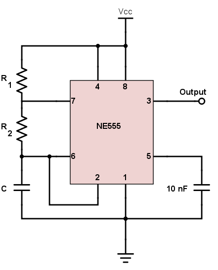
Schematic Diagram 555 Timer - 26 from www.allaboutcircuits.com Resistive network consists of three equal resistors and acts as a voltage divider. We have seen in the last few tutorials that the 555 timer can be configured with externally connected components as multivibrators, oscillators and timers, with timing intervals ranging from a few microseconds to many hours. The 555 timer is a chip that can be us… The 555 timer ic is an integrated circuit (chip) used in a variety of timer, delay, pulse generation, and oscillator applications. As we know 555 timer ic is one of the commonly used ic among students and hobbyists. The breadboard schematic of the above circuit is shown below. Circuits into the ever increasing ranks of timer users. Working modes of 555 timer ic.
The 555 timer is a simple integrated circuit (ic) that can be used in electronic circuits, projects, and a variety of applications like timer, pulse oscillator, delays, flip flop, etc
Adjustable on off timer(using 555 astable mode) in this circuit a timer with cyclic on off operations is designed. Rain alarm using 555 timer. A collection of 555 circuits using the 555 timer as an astable oscillator with different duty cycles. The 555 is also very versatile, and can be used. The 555 timer ic is an integrated circuit (chip) used in a variety of timer, delay, pulse generation, and oscillator applications. The 555 timer is a simple integrated circuit (ic) that can be used in electronic circuits, projects, and a variety of applications like timer, pulse oscillator, delays, flip flop, etc The time intervals can be used for keeping a relay controlled load on or activated for the desired amount of time and an automatic switch off once the delay period. The second 555 timer helper will extend the timers output duration without having to use large values of r1 and/or c1. Using the 555 timer ic in special or unusual circuits. The 555 timer is a chip that can be us… We connect a 100μf capacitor to the positive voltage supply and then to pin 2. Each mode of operation indicates a circuit diagram and its output. With this information you will learn how how the 555 works and will have the experience to build some of the circuits below.
The values of r1 and c1 determine how long the output will remain high. Referring to the timing diagram in figure 3, a low voltage pulse applied to the trigger input (pin 2) causes the output voltage at pin 3 to go from low to high. 555 timer ic is an integrated circuit used in a variety of timer, pulse generation circuit, and oscillator circuit applications. The time intervals can be used for keeping a relay controlled load on or activated for the desired amount of time and an automatic switch off once the delay period. These on off intervals can be adjusted by varying the 555 timer output and number of counter outputs.
555 Timer Circuit Schematic | Electronics projects, Timer ... from i.pinimg.com Adjustable on off timer(using 555 astable mode) in this circuit a timer with cyclic on off operations is designed. As discussed in the above section, the ic is in its standard monostable mode. The 555 timer is a simple integrated circuit (ic) that can be used in electronic circuits, projects, and a variety of applications like timer, pulse oscillator, delays, flip flop, etc The 555 can be used to provide time delays, as an oscillator, and as a flip flop element. We have seen in the last few tutorials that the 555 timer can be configured with externally connected components as multivibrators, oscillators and timers, with timing intervals ranging from a few microseconds to many hours. Simple 555 timer circuits & projects. In this project, we are using 555 timer ic to create various timer circuit like 1 min timer circuit, 5 min timer circuit, 10 min timer circuit, and 15 min timer circuit. Derivatives provide two or four timing circuits in one package.it was commercialized in 1972 by signetics.
The 555 timer is a chip that can be us…
The standard 555 timer ic is made of 2 diodes. The 555 can be used to provide time delays, as an oscillator, and as a flip flop element. The 555 timer ic is an integrated circuit (chip) used in a variety of timer, delay, pulse generation, and oscillator applications. Here is a simple and interesting hobby circuit that can be made using the popular 555 timer ic. The time intervals can be used for keeping a relay controlled load on or activated for the desired amount of time and an automatic switch off once the delay period. A monostable 555 timer is required to produce a time delay within a circuit. Working modes of 555 timer ic. Rain alarm using 555 timer. Derivatives provide two or four timing circuits in one package.it was commercialized in 1972 by signetics. In this mode, the circuit of the ic 555 timer produces the continuous pulses with exact frequency primarily based on the value of the two resistors and. Here, with the help of the 555 timer ic, we are eliminating the need of manually switching on or off the device. The 555 timer ic is an integrated circuit (chip) used in a variety of timer, delay, pulse generation, and oscillator applications. The 555 timer is a simple integrated circuit that can be used to make many different electronic circuits.
Circuits into the ever increasing ranks of timer users. As discussed in the above section, the ic is in its standard monostable mode. 555 ic timer block diagram 555 ic timer block diagram. The 555 timer ic is an integrated circuit (chip) used in a variety of timer, delay, pulse generation, and oscillator applications. With this information you will learn how how the 555 works and will have the experience to build some of the circuits below.
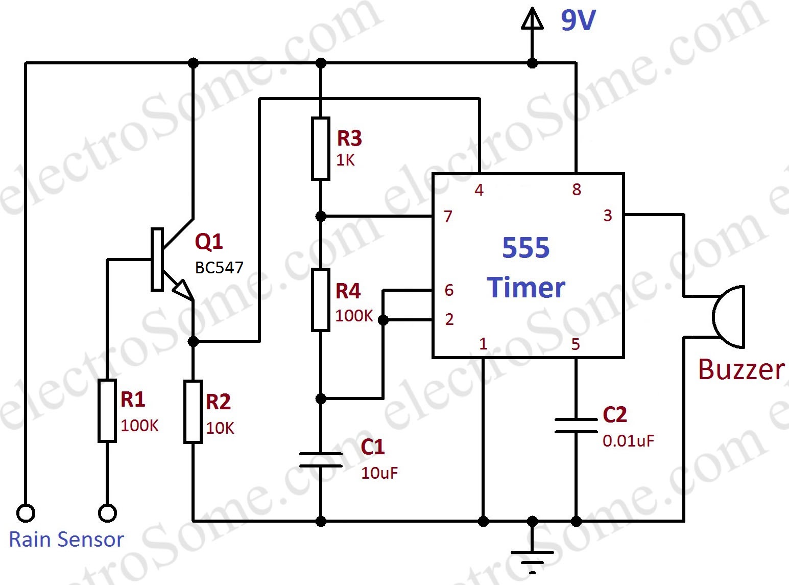
Rain Alarm using 555 Timer - Hobby Circuit from electrosome.com 555 timer circuits (133) browse through a total of 133 555 timer circuits and projects including the timer's datasheet. If a 10uf timing capacitor is used, calculate the value of the resistor required to produce a minimum output time delay of 500ms. Daman shah june 5, 2021. The circuits explained here are 10 best small timer circuits using the versatile chip ic 555, which generates predetermined time intervals in response to momentary input triggers. This led will be switched on when button s1 is pressed and switched off when button s2 is pressed. These on off intervals can be adjusted by varying the 555 timer output and number of counter outputs. The 555 is also very versatile, and can be used. In this mode, the circuit of the ic 555 timer produces the continuous pulses with exact frequency primarily based on the value of the two resistors and.
These on off intervals can be adjusted by varying the 555 timer output and number of counter outputs.
The values of r1 and c1 determine how long the output will remain high. 555 timer circuits (133) browse through a total of 133 555 timer circuits and projects including the timer's datasheet. A monostable 555 timer is required to produce a time delay within a circuit. 500ms is the same as saying 0.5s so by rearranging the formula above, we get the calculated value for the resistor, r as: These on off intervals can be adjusted by varying the 555 timer output and number of counter outputs. This circuit can be used as rain sensor, water overflow sensor or as a water level sensor. The standard 555 timer ic is made of 2 diodes. Adjustable on off timer(using 555 astable mode) in this circuit a timer with cyclic on off operations is designed. I am using a 12v 2.7ah nimh battery and i am using 4 (4.5v) solar panels in series with a power rating of 1.5 w (each panel) and current rating of 0.334. We connect a 100μf capacitor to the positive voltage supply and then to pin 2. Its name is derived from three 5k ohm resistors ,connected in series used in it.the timer ic can produce required waveform accurately. Rain alarm using 555 timer. The output voltage from the chip is around 1.5 v lower than vcc when high and around 0 v when low.